|
|
|
|
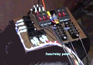
CONSTRUCTION OF FUSE PANEL |
||||||||||||
| 1. The base can be made of anything non-conductive. I made mine from a clipboard. I just cut it away from the metal clip. | ||||||||||||
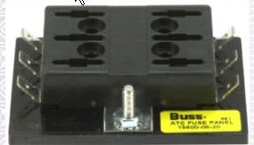
| 2. Get some small bolts, nuts, that will fit through the mounting holes in the relays and a little larger to fit through the fuse block or blocks depending on how many fuses you want. | ||||||||||||
| 3. Mount the parts as shown, unless you want to do it in a different way. | ||||||||||||
|
|
||||||||||||
| 4. Run a 14 gauge wire from your accessories pole of the starter to the fuse panel (also note that on mine I have a jumper between the two. | ||||||||||||
|
|
||||||||||||
| 5. I have two Junction Blocks on the fuse panel on mine. I also have one at the rear of the trike. My reasoning for them was to be able to run the wires to the front and back of the trike and be able to disconnect wires at the junction blocks in case I had to repair something. | ||||||||||||
|
||||||||||||
|
FUSE PANEL WIRING |
||||||||||||
|
CONNECTIONS |
| Run a 16 ga. wire from the fuse block (12VDC) each relay # 85 Run another to all relays to #30. You want 12VDC on pins #85 and #30. |
|
|
|
STARTER RELAY |
| Run a ground wire to one side of the starter switch. From the opposite side run another wire to the starter relay # 86. Run a 10 ga. wire to the starter motor from relay # 87 DO NOT ATTACH ANY WIRES TO #87A |
|
HORN RELAY |
| Run a ground wire to one side of the horn switch. From the opposite side of the switch, run a wire to the horn relay # 86. On the horn relay # 87 run a wire to the horn/s. Ground the horn. DO NOT ATTACH ANY WIRES TO # 87A. |
|
HEADLAMP RELAY |
|
Run a ground wire to one side of the headlight switch. Run the other side of the switch to the headlamp relay # 86. Run a wire to the low beam side of the headlight from # 87A on the relay (the headlight will come on when you turn on the ignition switch) Run another wire to the high beam side of the headlight from # 87 on the relay |
|
SPARE RELAY |
| It's up to you if you want to install the spare relay. If later you need to put one in it's good to have installed. | ||||||||
|
TURN SIGNALS |
||||||||
|
If you decide not to use the Bandlands turn signal module, shown elsewhere on this site, use a heavy duty turn signal flasher unit (2 prong) Run a fused wire to the flasher unit and from the other side go to the center pole of your turn signal switch. Then follow the wiring diagram found here. |
||||||||
|
|
||||||||
|
Now all you have to do is run fused wires to the items that require fuses......I hope this is going to help you. But remember this is just to show you what I have done. It isn't a recommendation for you to build one this way. I in no way will be held responsible for any damage or anything else if you build one using this as an example. |
||||||||
|
||||||||
|
|
||||||||
|
|