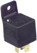
relays


A 12V, 30A  SPDT Relay


All relays perform some kind of electrical switching function. 

I use this type of relay for operating my handlebar switches, starter, headlights - Hi beam to Low Beams - horn button, turn signals, etc.  The illustration below shows one of my fuse/relay panels


An example of a relay operating a hi - low beam headlight switch is shown below


As you can see when the ignition is turned on the low beam light come on thru 30 and 87a.  When the coil is energized by turning on the hi beam switch on the handlebars sending 12volts to the coil to ground # 87 is then hot turning on the Hi beams.  You can add an off/on switch between the 12volt fuse panel and # 30 so you can turn the lights off and on when you wish.  All the other handlebar switches are operated in a like manor.


Example of a horn switch


Pins numbered 85 and 86 are the terminals that power the relay.  The relay uses very little current (about 1/10th AMP.

The switch used to control the relay can be fairly light duty as are the handle bar switches on the trike/bike.

In the case of this type relay, the actuating coil is not polarity sensitive, this means that "+" or "-" can be hooked to either 85 or 86. ( but NOT if there is a diode wired across the coil. One of these terminals must be grounded, these relays do not have a case ground.

Pin number 30 is common, the in-coming load wire (12vdc) would be hooked to this pin.

Pin's numbered 87 and 87a are the outputs side of number 30.  The number 87a pin is a normally closed contact.  This means if the actuating coil is not powered, number 30 and 87a are connected together.  If the coil has power applied, 30 and 87a will open and 12V will be applied to 87.  Power to the coil will be needed to close 87 and 30.


Ok, there you got  the idea, basically all your other relay switches are installed in the same manor.


Got an email from a guy who wants to use this relay to activate the clutch in an auto stick tranny.  You need to send a ground to the tranny from the handle bar switch.  So here is the diagram as I understand it.


This information provided as an option to those who wish to use it. It is recommended only to those who have some familiarity with such practices and electronics in general. Trikerdon  is not responsible for any damages sustained from mishandling of products or incorrect interpretation of this information. Use at your own risk.