|
|
|
|
WIRING YOUR TRIKE (3) |
||
|
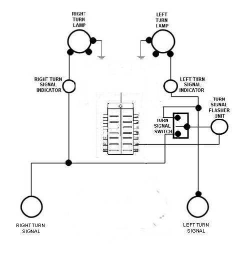
Now for the turn signals. I recommend a heavy duty flasher unit. If you tow a trailer and use the extra lights you will need it. |
||
|
Run a 16 gauge wire from your fuse panel to the turn signal flasher unit. Then run a 16 gauge wire from the unit to your turn signal switch. From the left side of the switch run the 16 gauge wire to the front and rear turn signal lamps (again I use the terminal block for both wires) Do the same from the right side of the turn signal switch. |
||
|
|
||
|
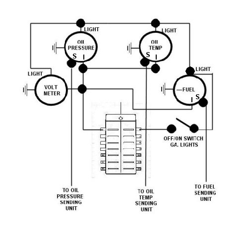
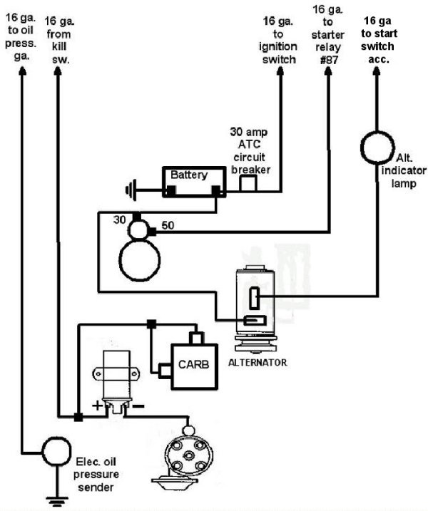
The Gauges are wired as shown below. Use 16 Gauge wire. |
||
|
|
||
|
|
||
|
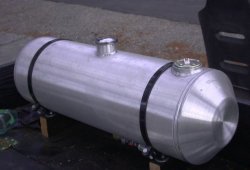
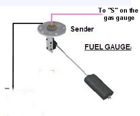
This sending unit is used with the round aluminum dune buggy type fuel tanks. |
||
|
This is the one I use. I had the hole for the sending unit put in for me. |
||
|
|
||
|
|
||
|
Time to wire up the engine |
||
|
|
||
|
NOTE The alternator is grounded through the pedestal and into the engine block. This is why there must be a good grounding strap from the transaxle to the chassis and from the chassis to battery. The ground path has to carry 50 amps from the alternator body to battery, and about 50 amps from the battery ground to starter body.
|
||
|
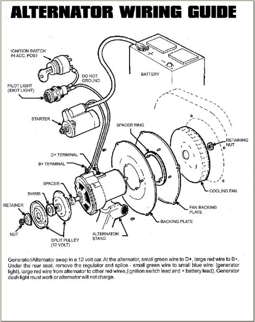
GENERATOR WIRING GUIDE |
||
|
|
||
|
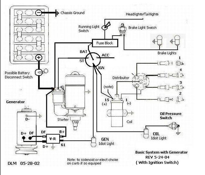
Here is a basic wiring diagram with generator |
||
|
|
||
|
How to Polarize Your Generator
|
||
|
IT IS NOT NECESSARY TO POLARIZE AN ALTERNATOR |
||
|
NOTES |
||
Necessity for the Alternator Warning LightIt is absolutely essential that the (D+) terminal on the alternator be connected to a functioning "Alt" warning light in the instrument cluster. If this light is missing or defective, the alternator will NOT charge the battery. An LED light won't work for this purpose. LED's are diodes and will not allow current to flow in the opposite direction. With the LED, it would see the 12 volts, but the reverse flow 2 volts would be stopped by the diode nature of the LED. Your battery will not charge if the Alt light is burnt out. |
||
|
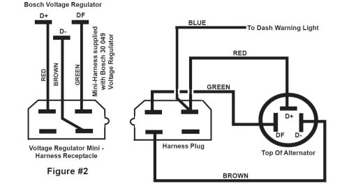
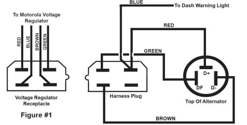
BOSCH AND MOTOROLA EXTERNAL REGULATOR ALTERNATOR WIRING Volkswagen supplied Alternators and Voltage Regulators from two sources during this model year period that utilized External Voltage Regulators. The Motorola Voltage Regulator (See Figure # 1 below) is no longer available, but the Bosch Regulator (Bosch 30 049)(SeeFigure # 2 below) can be used with either Alternator if the mini-harness/receptacle supplied with the Voltage Regulator is utilized. Please note the slight (but important) differences in the two diagrams below. Note that the Blue Wire coming from the Motorola Voltage Regulator
|
||
|
||
|
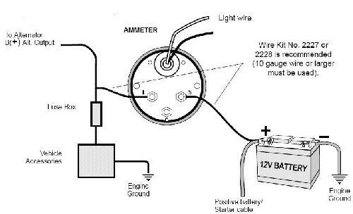
AMP METER CAUTION DO NOT CONNECT THE AMMETER ACROSS THE BATTERY Example wiring of a typical Ammeter installation Consult vehicle Mfr. for specific wiring details and safety considerations
|
||
|
Have your maximum alternator output tested. Choice of improper ammeter rating and/or wire size, and any loose connections can cause dangerous overheating, which could lead to a fire in the vehicle. Ammeter and wire should have a capacity of at least 10 amps more than your vehicle's maximum alternator output. 1. . Disconnect negative (-) battery cable. (Wear safety glasses.) 2. 10 GA wire or larger must be used 3. IMPORTANT: Verify that base nuts on both meter terminals are tight. Tighten base nuts prior to installing terminal lugs and wires. |
||
|
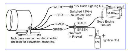
TACHOMETER WIRING |
||
|
|
||
|
|